Showing posts with label 8085 microprocessor. Show all posts

Saturday, 15 March 2014

INTERNAL STRUCTURE OF INTEL 8085

Internal structure of 8085:
                                                   The functional block diagram of 8085


It consists of five essential blocks.

(1)    ARITHMETIC LOGIC SECTION

(2)     REGISTER SECTION

(3)     THE INTERRUPT CONTROL SECTION

(4)     SERIAL I/O SECTION

(5)     THE TIMING AND CONTROL UNIT

 ACCUMULATION (A): It is a 8 bit tri state register accessible to the user. Its tri state output is connected to the internal bus in addition, it has a two state 8 bit output. The content of the accumulator is always available at this two state output as the accumulator can be manipulated

Wednesday, 8 May 2013

INSTRUCTION SET: 

An instruction set is a command given to the computer to perform specific operation. it contains command , operand and address of source  and destination.

8085 Microprocessor have five types of instruction set :  

  • Data transfer instruction

  • Arithmetic  instructions

  • Logical instructions

  • Control instructions

  • Branching instructions 

    Data transfer instructions:   Instructions, which are used to transfer data from one register to another register, from memory to register or register to memory, come under this group. Examples are: MOV, MVI, LXI, LDA, STA etc. When an instruction of data transfer group is executed, data is transferred from the source to the destination without altering the contents of the source.


    • MOV r1, r2 (Move Data; Move the content of the one register to another).  [r1] <-- [r2]
    • MOV r, m (Move the content of memory register). r <-- [M]
    • MOV M, r. (Move the content of register to memory). M <-- [r]
    • MVI r, data. (Move immediate data to register). [r] <-- data.
    • MVI M, data. (Move immediate data to memory). M <-- data.
    • LXI rp, data 16. (Load register pair immediate). [rp] <-- data 16 bits, [rh] <-- 8 LSBs of data.
    • LDA addr. (Load Accumulator direct). [A] <-- [addr].
    •  STA addr. (Store accumulator direct). [addr] <-- [A].
    • LHLD addr. (Load H-L pair direct). [L] <-- [addr], [H] <-- [addr+1].
    • SHLD addr. (Store H-L pair direct) [addr] <-- [L], [addr+1] <-- [H].
    • LDAX rp. (LOAD accumulator indirect) [A] <-- [[rp]]
    • STAX rp. (Store accumulator indirect) [[rp]] <-- [A].
    • XCHG. (Exchange the contents of H-L with D-E pair) [H-L] <-->  [D-E].


     Arithmetic instructions:  The instructions of this group perform arithmetic operations such as addition, subtraction; increment or decrement of the content of a register or memory. Examples are: ADD, SUB, INR, DAD etc.


    •  ADD r. (Add register to accumulator) [A] <-- [A] + [r].DAA (Decimal adjust accumulator) .
    • ADD M. (Add memory to accumulator) [A] <-- [A] + [[H-L]].
    • ADC r. (Add register with carry to accumulator). [A] <-- [A] + [r] + [CS].
    • ADC M. (Add memory with carry to accumulator) [A] <-- [A] + [[H-L]] [CS].
    • ADI data (Add immediate data to accumulator) [A] <-- [A] + data.
    • ACI data (Add with carry immediate data to accumulator). [A] <-- [A] + data + [CS].
    • DAD rp. (Add register paid to H-L pair). [H-L] <-- [H-L] + [rp].
    • SUB r. (Subtract register from accumulator). [A] <-- [A] – [r].
    • SUB M. (Subtract memory from accumulator). [A] <-- [A] – [[H-L]].
    • SBB r. (Subtract register from accumulator with borrow). [A] <-- [A] – [r] – [CS].
    • SBB M. (Subtract memory from accumulator with borrow). [A] <-- [A] – [[H-L]] – [CS].
    • SUI data. (Subtract immediate data from accumulator) [A] <-- [A] – data.
    • SBI data. (Subtract immediate data from accumulator with borrow). [A] <-- [A] – data – [CS].
    • INR r (Increment register content) [r] <-- [r] +1.
    • INR M. (Increment memory content) [[H-L]] <-- [[H-L]] + 1.
    • DCR r. (Decrement register content). [r] <-- [r] – 1.
    • DCR M. (Decrement memory content) [[H-L]] <-- [[H-L]] – 1.
    • INX rp. (Increment register pair) [rp] <-- [rp] – 1.
    • DCX rp (Decrement register pair) [rp] <-- [rp] -1.


    Logical instructions: The Instructions under this group perform logical operation such as AND, OR, compare, rotate etc. Examples are: ANA, XRA, ORA, CMP, and RAL etc.

    • ANA r. (AND register with accumulator) [A] <-- [A] ^ [r].
    • ANA M. (AND memory with accumulator). [A] <-- [A] ^ [[H-L]].
    • ANI data. (AND immediate data with accumulator) [A] <-- [A] ^ data.
    • ORA r. (OR register with accumulator) [A] <-- [A] v [r].
    • ORA M. (OR memory with accumulator) [A] <-- [A] v [[H-L]]
    • ORI data. (OR immediate data with accumulator) [A] <-- [A] v data.
    • XRA r. (EXCLUSIVE – OR register with accumulator) [A] <-- [A] v   [r]
    • XRA M. (EXCLUSIVE-OR memory with accumulator) [A] <-- [A] v  [[H-L]]
    • XRI data. (EXCLUSIVE-OR immediate data with accumulator) [A] <-- [A]
    • CMA. (Complement the accumulator) [A] <-- [A]
    • CMC. (Complement the carry status) [CS] <-- [CS]
    • STC. (Set carry status) [CS] <-- 1.
    • CMP r. (Compare register with accumulator) [A] – [r]
    • CMP M. (Compare memory with accumulator) [A] – [[H-L]]
    • CPI data. (Compare immediate data with accumulator) [A] – data.The 2nd byte of the instruction is data, and it is subtracted from the content of the accumulator. The status flags are set according to the result of subtraction. But the result is discarded. The content of the accumulator remains unchanged.
    • RLC (Rotate accumulator left) [An+1] <-- [An], [A0] <-- [A7],[CS] <-- [A7].
      The content of the accumulator is rotated left by one bit. The seventh bit of the accumulator is moved to carry bit as well as to the zero bit of the accumulator. Only CS flag is affected.
    • RRC. (Rotate accumulator right) [A7] <-- [A0], [CS] <-- [A0], [An] <-- [An+1].
      The content of the accumulator is rotated right by one bit. The zero bit of the accumulator is moved to the seventh bit as well as to carry bit. Only CS flag is affected.
    • RAL. (Rotate accumulator left through carry) [An+1] <-- [An], [CS] <-- [A7], [A0] <-- [CS].
    • RAR. (Rotate accumulator right through carry) [An] <-- [An+1], [CS] <-- [A0], [A7] <-- [CS]

  • Branching instructios:  This group includes the instructions for conditional and unconditional jump, subroutine call and return, and restart. Examples are: JMP, JC, JZ, CALL, CZ, RST etc.

    • JMP addr (label). (Unconditional jump: jump to the instruction specified by the address). [PC] <-- Label.
    • Conditional Jump addr (label): After the execution of the conditional jump instruction the program jumps to the instruction specified by the address (label) if the specified condition is fulfilled. The program proceeds further in the normal sequence if the specified condition is not fulfilled. If the condition is true and program jumps to the specified label, the execution of a conditional jump takes 3 machine cycles: 10 states. If condition is not true, only 2 machine cycles; 7 states are required for the execution of the instruction.
      • JZ addr (label). (Jump if the result is zero)
      • JNZ addr (label) (Jump if the result is not zero)
      • JC addr (label). (Jump if there is a carry)
      • JNC addr (label). (Jump if there is no carry)
      • JP addr (label). (Jump if the result is plus)
      • JM addr (label). (Jump if the result is minus)
      • JPE addr (label) (Jump if even parity)
      • JPO addr (label) (Jump if odd parity)
    • CALL addr (label) (Unconditional CALL: call the subroutine identified by the operand)CALL instruction is used to call a subroutine. Before the control is transferred to the subroutine, the address of the next instruction of the main program is saved in the stack. The content of the stack pointer is decremented by two to indicate the new stack top. Then the program jumps to subroutine starting at address specified by the label.
    • RET (Return from subroutine)
    • RST n (Restart) Restart is a one-word CALL instruction. The content of the program counter is saved in the stack. The program jumps to the instruction starting at restart location.

  •  Control instructions:   This group includes the instructions for input/output ports, stack and machine control. Examples are: IN, OUT, PUSH, POP, and HLT etc


    • IN port-address. (Input to accumulator from I/O port) [A] <-- [Port]
    • OUT port-address (Output from accumulator to I/O port) [Port] <-- [A]
    • PUSH rp (Push the content of register pair to stack)
    • PUSH PSW (PUSH Processor Status Word)
    • POP rp (Pop the content of register pair, which was saved, from the stack)
    • POP PSW (Pop Processor Status Word)
    • HLT (Halt)
    • XTHL (Exchange stack-top with H-L)
    • SPHL (Move the contents of H-L pair to stack pointer)
    • EI (Enable Interrupts)
    • DI (Disable Interrupts)
    • SIM (Set Interrupt Masks)
    • RIM (Read Interrupt Masks)
    • NOP (No Operation)


REGISTER SET OF 8085:

  • 8085 have six general purpose register to store 8- bit data during execution.
  • these registers are B,C,D,E,H and L.
  • they can combine to perform 16-bit operation and denoted as BC,DE and HL pair.  
ACCUMULATOR(A) :
  • The accumulator is an 8-bit register .
  • This register is a part of ALU unit
  • This register is used to store 8-bit data and to perform arithmetic and  logic operation.
  • The result of an operation is stored in accumulator
FLAG REGISTER:-
  • flag register are used to test data condition.
  • 8085 have five flag register of 8-bit.
  • these are following: Zero flag(Z), Sign flag(S), Carry flag(CY), Parity flag(P) and Auxiliary flag(AU)
Sign flag(S):  After execution of any arithmetic and logic operation, if the result of D7 is 1,sign flag is set otherwise reset.
Zero flag(S): If the result of arithmetic or logic operation is zero then it is set otherwise reset.

Carry flag(CY): If any arithmetic and logic operation produce any carry then carry flag is set otherwise reset.
Parity flag(P): If result of any arithmetic and logic operation contains even no of 1's then it is set otherwise reset.
Auxiliary carry flag(AU): When D3 generates any carry during arithmetic and logic operation then it is set otherwise reset.


ARITHMETIC LOGIC UNIT (ALU):

  • It is used to perform arithmetic operation like (addition, subtraction, multiplication and division) and logic operation like (AND, OR and EX-OR etc)
  • It receives data from accumulator and registors.
  • According to results it set or reset the flags.
PROGRAM COUNTER (PC)

  • This 16-bit register deals with sequencing the execution of instructions. 
  • This register is a memory pointer. Memory locations have 16-bit addresses, and that is why this is a 16-bit register.
  • The microprocessor uses this register to sequence the execution of the instructions.The function of the program counter is to point to the memory address from which the next byte is to be fetched. When a byte (machine code) is being fetched, the program counter is incremented by one to point to the next memory location  
STACK POINTER (SP)
  • The stack pointer is also a 16-bit register used as a memory pointer. 
  • It points to a memory location in R/W memory, called the stack. 
  • The beginning of the stack is defined by loading 16-bit address in the stack pointer. 
INSTRUCTION  REGISTER/DECODER:

Temporary store for the current instruction of a program. Latest instruction sent here from memory prior to execution. Decoder then takes instruction and ‘decodes’ or interprets the instruction. Decoded instruction then passed to next stage.

Memory Address Register:  Holds address, received from PC, of next program instruction. Feeds the address bus with addresses of location of the program under execution.

Control Generator:  Generates signals within uP to carry out the instruction which has been decoded. In reality causes certain connections between blocks of the uP to be opened or closed, so that data goes where it is required, and so that ALU operations occur.

Register Selector  This block controls the use of the register stack in the example. Just a logic circuit which switches between different registers in the set will receive instructions from Control Unit.

General Purpose Registers  uP requires extra registers for versatility. Can be used to store additional data during a program. More complex processors may have a variety of differently named registers. 

Timing and Control unit:

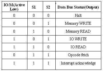
  • It has three control signals ALE, RD (Active low) and WR (Active low) and three status signals IO/M(Active low), S0 and S1

  • ALE is used for provide control signal to synchronize the components of microprocessor and timing for instruction to perform the operation. 

  • RD (Active low) and WR (Active low) are used to indicate whether the operation is reading the data from memory or writing the data into memory respectively.
  • IO/M(Active low) is used to indicate whether the operation is belongs to the memory or peripherals.


Monday, 6 May 2013

The functional block diagram or architecture of 8085 Microprocessor is very important as it gives the complete details about a Microprocessor.


 Fig. shows the Block diagram of a Microprocessor.


8085 BUS STRUCTURE
 address bus:-
  • The address bus is a group of 16 lines generally identified as A0 to A15. 
  • The address bus is unidirectional: bits flow in one direction-from the MPU to peripheral devices.
  • The MPU uses the address bus to perform the first function: identifying a peripheral or a memory location.  

DATA BUS:-
  • The data bus is a group of eight lines used for data flow.
  • These lines are bi-directional - data flow in both directions between the MPU and memory and peripheral devices.
  • The MPU uses the data bus to perform the second function: transferring binary information.
  • The eight data lines enable the MPU to manipulate 8-bit data ranging from 00 to FF (28 = 256 numbers).
  • The largest number that can appear on the data bus is 11111111

 Control bus:-
  • The control bus carries synchronization signals and providing timing signals.
  • The MPU generates specific control signals for every operation it performs. These signals are used to identify a device type with which the MPU wants to communicate.


DMA Request Signal:
HOLD and HLDA:-HOLD is an active high input signal used by the other controller to request microprocessor about use of address, data and control signal. The HOLD and HLDA signal are used for direct memory access(DMA). DMA controller receives a requests from a device and in turn issues the HOLD signal to the microprocessor.
The processor releases the system bus and then acknowledges the HOLD signal with HLDA signal. The DMA transfer thus begins.


logic schematic diagram of 8085
Serial Input Output port:-
SID and SOD:-These pins are used for serial data communication.


Introduction:-


Today the microprocessor based products have revolutionized every area of human  activity and have made a deep impact on quality of life. Right from small chip to supercomputer Microprocessor have become an integral part of the system. Microprocessor evolved from the developments in computer. One such microprocessor is Intel’s 8085, which is most popularly used and regarded as a basic microprocessor. The microprocessors operation can be described through the organization of computer model.

Generally a computer organization is as follows

INPUT> ALU+CONTROL UNIT+MEMORY> OUTPUT
      (1)                           (2)                                                  (3)

Unit 2 is generally replaced with microprocessor. So a microprocessor can be represented as :
Microprocessor=ALU+Registers+Program Counter+Control and Timing circuit+Stack Pointer +Interrupt Circuit.

PIN DIAGRAM:-

8085 is a general purpose microprocessor having 40 pins and works on single power supply. To study the pin diagram we group
 the signals into 6 categories:

1.Power Supply
2.Interrupt Signals
3.Address and Data bus
4.Control and Status signals
5.Serial I/O Port
6.DMA Request Signals


 Power supply and Clock frequency signals:


  • VCC:-Vcc is to be connected to +5V power supply.
  • Vss:-Ground reference
  • X1 and X2:- This pin is used for providing the clock frequency to the microprocessor. Generally Crystal oscillator or LC oscillator is used to generate the frequency.
  •  The frequency generated here is internally divided into two.As we know that the basic operating timing frequency of the microprocessor is 3 MHz so 6 MHz frquency is applied.
  • CLK (output)-Clock Output is used as the system clock for peripheral and devices interfaced with the microprocessor.

 Multiplexed Address / Data Bus:


  • AD0-AD7:-These are multiplexed address and data bus. So it can be used to carry the lower order 8 bit address as well as the data. Generally these lines are demultiplexed using the Latch.
  • During the opcode fetch operation, in the first clock cycle the lines deliever the lower order address bus  A0-A7.
  • In the subsequent IO/M read or write it is used as data bus D0-D7. CPU can read or write data through these lines.
  • A8-A15:- These are address bus used to address the memory location.

 Interrupt signal:

  • Pin 6 to 11:- These pins are used for interrupt signals. Generally and external devices are connected here which requests the microprocessor to perform a particular task.
  • There are 5 pins for hardware interrupts-
    TRAP, RST7.5, RST 6.5, RST5.5 and INTR
  • INTA is used for acknowledgement. Microprocessor sends the acknowledgement to external devices through the INTA pin. 

Control And Status Signal:

  • S0 and S1:-It is used for the status signal in microprocessor
  • .ALE(Airthmetic Latch Enable):-This signal is used to capture the lower address presented on multiplexed address and data bus.
  • RD:-This is active low input generally
     used for reading operation.
  • WR:-This is active low input used for writing operation.
  • IO/M:-This pin is used to select the memory or input-output through which we want to communicate the data.
  • READY:-As we know that memory and input -output have slower response than microprocessor. So a microprocessor may now be able to handle further data till it completes the present job. So it is in waiting state. As it completes the present job it sets the READY pin. Microprocessor enters into wait state while READY pin is disabled.
  • RESET IN:-This is active low input. This pin is used to reset the microprocessor. An active low signal applied to this pin reset the program counter inside the microprocessor. The busses are tristated.
  • RESETOUT:-If we want to reset the external devices connected to the microprocessor then a signal applied to this pin resets the external devices.